Hello everyone. If you’re reading this post recently after being posted, I would like to wish you a very happy festivities period, as well as a New Year 2018. This year has been a very productive and interesting year for The Tinkering Corner, we (As in myself) have meet a ton of people from the community this year, as well as made new friendships with individuals from all over the world. Hopefully this next year will be as good or better for us, and we will be able to reach more individuals and encourage the open spread of ideas.
Back to the point of this post of this post, if you have been recently viewing the latest series of videos of my Youtube channel, you must have noticed the CNC machine build. This CNC machine, codenamed “Resonante” (Which means “Resonant” in the Spanish language) is a home made three axis CNC machine with the sole purpose of creating home made Copper clad PCBs at home. Please refer to these videos in order for you to not get completely lost throughout this post.

The real purpose of this machine was to be able to easily go from a circuit design to a prototype in mere hours, cutting the wait times from PCB manufacturing houses (Fabs). Being able to design this machine was a very interesting experience, I went from knowing nothing about the process of DYI PCB creation to becoming an expert in the basics of said process (If that even makes sense) while honing my 3D CAD design, circuit design, and prototyping skills. The aim of this post is to give you a very general sense as to the capabilities of this machine, what it could do, and what it could not do. In the end I also decided to move on to a new version of this machine, and I will also explain why.
As stated before, this machine was sole purpose was to create home made PCB circuit boards. The machine would allow me to be able to design a circuit in a software such as KiCad, export it to a PCB routing Cam software (Such as Flatcam) and then send it to the CNC machine via Gcode. The way in which this machine created the PCBs was by engraving isolation tracks in Copper clad sheets using a fast spinning, high torque rotatory tool with a carving bit, which will remove Copper regions specified by the Cam software. This in the end will create tracks, which were isolated from the general Copper areas, through which current will flows. This process can be faster/easier than the traditional process of etching, but can also produce lower quality PCBs. The Resonante was also built to be able to produce double-sided PCBs just by flipping the Copper clad board when one side was done being routed.

My goal when designing this machine was to design an affordable machine, which most of it’s parts could be 3D printed and/or sourced from different vendors to then put together at home. I wanted it to be as flexible and modular a possible, this is why I used 1515 Misumi extrusions as core of the frame. These Aluminum extrusions allow you to move parts around, expand or shrink the machine very easily by cutting them to size, while also being extremely rigid. In hindsight I should have purchased 2020 extrusions, but 1515 is what I had around at the time. Which leads me to my next point, all the parts that were used in the build of this machine were parts that I had around, which constrained the design of this machine. All the plastic parts were printed in Zyltech Red/White PLA, which surprisingly were very rigid and didn’t give me any real issues. The benefit of using 3D printed parts is that they can be easily modified in CAD design software to improve them and iterate on them very easily and quickly.
For the mechanics and motion, the machine used Nema17 stepper motors, which are attached to the carriages by either GT2 belts (X and Y axis) or 5/16 Threaded rods (Z axis), very similar to how 3D printers mechanics tend to be set up. For the spindle, I first started using a 12/24V motor from Banggood which seemed up for the task, but then had to switch to a beefy 110V rotatory tool. In order to be able to control the Stepper motors of this machine, I used a Arduino Uno based CNC kit which included an Arduino Uno, an Arduino Uno compatible CNC shield and 4 Polulu Stepper drivers (Really only needed 3 of them). They allowed me to control all the motors, checking the endstop status and to control the spindle. To power all the electronics I used a 150W power supply which ran everything at 12V. While I was using the Banggood motor, since it was a DC motor, I was able to use a Solid State Relay in order to switch it on and off, as well as to variate it’s speed. However, when I switched to the rotatory tool I decided to power it and change speeds manually.
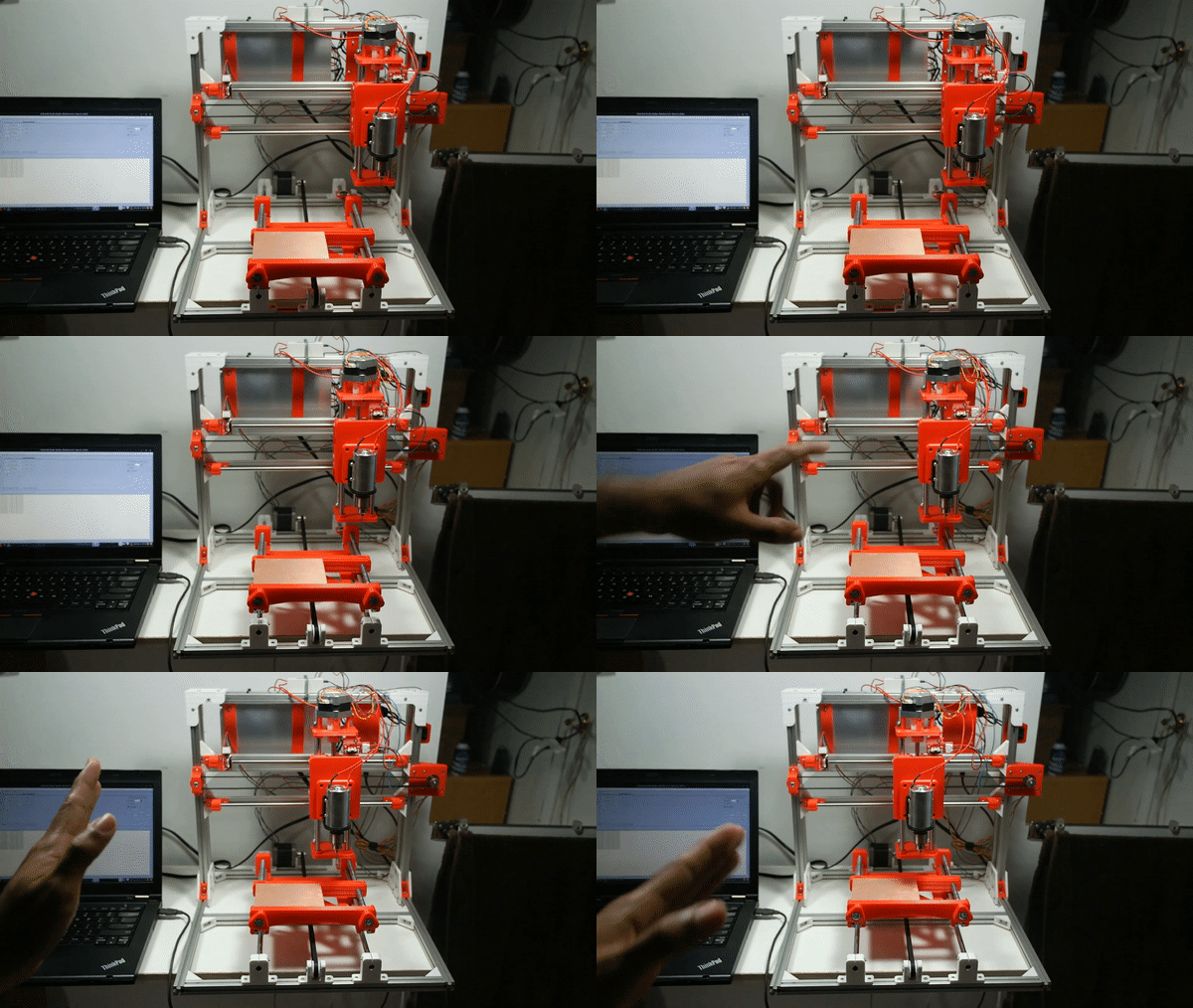
The Arduino used GRBL, a very versatile firmware that is used to control CNC machines (Sort of like the Marlin firmware, but for CNC machines). It allows you to change settings of it on the fly without having to reflash the firmware. I really came to love it because of it’s simplicity and ease of use. To be able to interface and control the Resonante CNC machine I used the cross platform software called Universal Gcode Sender which is a small Java application that allows you to interface with CNC controllers, giving you a very minimalist UI. The features in it were good enough for what I was doing and it was not over-complicated like other pieces of software out there. Universal Gcode Sender is also rather good at running instructions from a text file or Gcode file.

However, the real question is, how do you generate such Gcode instructions for making PCBs? This was in fact one of the biggest road blocks that I faced during the build of this machine. There are some software packages that allow you to do said task, but they are either deprecated, not cross platform, extremely complicated to use or do not work at all. The most decent one that I found out of the ones out there was Flatcam. Flatcam was made specifically for PCB routing and it does it well, however, it does fall in the “extremely overcomplicated” category for sure. The shear amount of settings and things you can tweak will make your head spin and the amount of testing that you will have to do to get your PCBs coming out “just right” takes a lot of patience and perseverance. If you decide to go through this horrible testing experience, be sure to have some noise canceling headphones and put aside a whole day or two just for troubleshooting. Now that we have thoroughly discusses the design constrain and choices for this machine, I would like to us to talk about what worked in this machine (based on it’s intended use) and what did not work.
Overall there were many things in this machine which worked rather well considering that this machine was built by someone who is not a Mechanical Engineer or that has much experience with mechanics. One of those elements that surprised me by how well it worked were the mechanics of the machine. The X, Y and Z axis moved rather smoothly, did not skip any steps or jerked at all. Even the Z axis, which was using a very rough 5/16 threaded rod was moving rather smoothly after some tweaking, giving me a very fine resolution in the Z axis. The belt driven motions did not have any issues as well. However, they did create issues because of the routing process which I will talk about later. The 8mm rods used in the every axis also helped to provide very smooth motion without binding. If I were to design a new machine like this one, I would have used rods with a bigger diameter to provide with more rigidity.
The clamping mechanism also surprised me as to how well it did work. In video #4 of the series tittled “New DYI CNC Machine: Vice And Enstops”, I showed the viewers how I could clamp a PCB and move the machine from it. That should be proof enough of how well that vice held those in place. The Resonante needed this rigid vice in order to be able to firmly hold the PCBs as they were being milled, and from my test it tended to perform the task perfectly. In the future I might design a standalone version of this vice just for soldering, because why not!

One of the side goals of this machine was modularity. Meaning that parts could be easily swapped to improve it, as well as so it’s application could be easily changed. To fulfill this goal, I designed the Z carriage in a way that it would allow for the swapping of tools by swapping the holding bracket of the tool. Attaching a microscope to it could have allowed me to analyze a small PCB easily or turn it into a pick and place machine to assemble SMD PCBS (With some effort of course).
Speaking of modularity, another thing that was very useful was the electronics configuration of it and how modular all the components of it were. Since I was using readily available components in the build, such as Nema17 Stepper motors or an Arduino based CNC board, if anything broke or needed an upgrade, it was very easy to swap components. If you are not familiar with Nema17 stepper motors, they come in different lengths and the longer the motor, the more holding torque it can achieve, this while keeping the same mounting profile. This feature allowed me to test different motor sizes and see which length would give me the best performance on this machine without skipping steps. The Arduino based controller was also a plus since if everything went completely wrong and the whole controller caught fire, it would have set me about $15 behind. These days Arduinos are so cheap that it is worth less to buy a new controller than to try to fix it if it ever broke. Having such jellybeans components control a whole CNC machine is honestly impressive. Combine that with Grbl and you will have a recipe for some cool stuff to happen.

Even if this CNC had some pretty good features that made it a really good machine, it did had a lot of drawbacks which made me rethink whether I should be using this machine for this application. One of those drawback was the noise produced by the milling operation. Since this machine is not enclosed, and it is using a rotatory tool to mill the PCBs, while milling the machine is insanely loud. It is loud enough that it would make my neighbors uncomfortable since the machine could be heard from the outside of my apartment. Just imagine having something so loud in the same room that you’re trying to do basically anything else and that’s an automatic headache waiting to happen.
Another key factor that lead me to completely stop milling with this machine was the safety aspect of milling PCBs. The double sided Copper Clad boards that I am using are made by sandwiching two thin sheets of Copper on a layer of FR-4 which is a glass-reinforced epoxy laminate. Milling FR-4 releases small glass particles into the air, which when inhaled could cause serious respiratory issues. Not only that, but also the Copper dust created by the milling process could be harmful for your health. I have to admit, I completely ignored these safety facts during the build process of it and by the time the build was done, it was already too late. A strong vacuum could have helped with both these small type of particles but it for sure would have not been strong enough. There is one way to mitigate the issue which some people use, which is to mill your PCBs while they are dipped in a pool of oil, so particles do not fly out and keeping your cutting head sharp for a longer time. During my tests, what I did was to constantly oil the surface which was being cut in order for the oil to hold all particles that would end up flying off, but on the long run it would have not been enough.
Another problem, which was mostly visible when the machine going through a routing operation was the rigidity of the machine and other issues which will crop up when the machine had to deal with high loads. Since I was using GT2 belts, which are mostly used for applications where there is no active load applied to the machine, when under load, these belts would stretch and the cutting tool will lag back by about 2mm and then jump forwards. This created a gap in the cutting surface, completely ruining the process itself. This could be fixed by changing the belts for threaded rods or leadscrews, but then we still have the two previous issues to deal with still.
The last nail in the coffin of this machine was the cost V.S. quality of this process. Yes, this CNC machine is a quick prototyping tool, and as such it would give me rough prototypes which I could then send to fabrication house. However, when places like OSH Park can give you 3 PCBs for $5 per square inch, it really makes you just skip the home prototyping step completely. Not only that but there are places in China who will give you far cheaper prices with bigger volumes. However, the waiting times still make home PCB fabrication very attractive as many of these places can take more than a week to fulfill your order and ship it.

Sadly, because of all the drawbacks of this process, I will not be using this method of creating PCBs. It seems far too dangerous (and loud!) to be done in a room. However, I do believe we could reach a middle ground since my design had a lot positive aspects which a future design could inherit and build on. This is why, I will be moving on to creating a fully redesigned version 2 of the Resonante CNC. However, before moving on to a new design, I feel that the only right thing to do would be to completely open the files for the first version of the Resonante machine. All the files will be on Github, shared under an open license which will allow modifications to be made to the machine. Feel free to take it and do whatever you like with it!
So, here is what I have in mind for the new version of the Resonante, the machine will be a laser based system, which would be the first step of chemical etching the PCBs. The machine will be in the shape of a big rectangular box, containing all the moving components inside of itself. It will have an X and Y axis only, and it will be moving around a 2.5W laser. The method of etching that we will be using is one which first we paint the side of the Copper clad board which we would like to have our circuit in with a black, non reflective paint which we will then user the laser in our machine to methodically vaporize the shape of our tracks in our circuit.
After vaporizing the paint, then we have to etch our PCB with chemicals such as FeCl3 (Ferric Chloride) in order to create the track separations for our current to flow through. The process is very similar to the one done with paper transfer, but this one is simpler and effortless. I did take a lot of inspiration from videos in the topic created by the Youtubers Marco Reps, Tech2C and EcProjects. For this design, I will also have some constrains for the machine. This machine needs to be easy to enclose, because I will be vaporizing acrylic paints which can create toxic fumes. What this means is that all the components of the machine need to reside within the machine, and there has to be a way of extracting the fumes to the outside as well. The enclosure of the machine would also need to be completely dark and let no light through. Dealing with a laser can be very dangerous, just looking at the laser while it is in active use could harm your vision. I would also like that if someone comes into my room, and they are not wearing eye protection, they will not be instantly blinded when they try to figure out what am I doing.
This new version will also inherit from the successes of the older version by using the same modular mechanics, electronics and printed parts. I am still not yet sure of how I am going to achieve the mechanics of the whole build, or if I will be adding a Z axis at all (Not really needed other than for focusing, which could always be done manually). I will also document the build of the machine in this here website and give you updates as I work on it.
Although the the first version of the Resonante CNC was not a total success, I did learn myriad of things which I would have not learned otherwise. Like my other custom 3D Printer projects, this project also helped me hone my CAD design abilities a lot, which I am very grateful for. Which is in fact the spirit of my website and my Youtube Channel, I try new things to learn from them, while showing you guys so you can also learn from them. Anyways, I think this post is already long enough. Please remember be sure to check back later or subscribe to the RSS feed so you will be able to see the newest posts regarding the version 2 of the Resonante machine.


